KGO Transmitter
Circuit Diagram, 1929
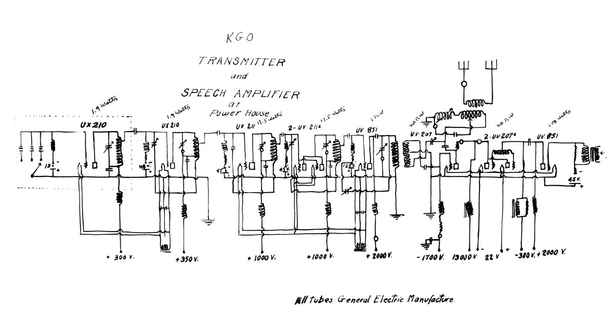
This
circuit diagram of the KGO transmitter facility was submitted to the
Federal Radio Commission as part of the station's license renewal
application in October, 1929. It describes the construction of
the custom-built General Electric transmitter, serial number "KGO-1".
There were undoubledly several transmitters and numerous
modifications made between KGO's original 1924 air date and the
creation of this drawing.
Here is a detail description of the equipment for our "technically-minded" readers:
Here is a detail description of the equipment for our "technically-minded" readers:
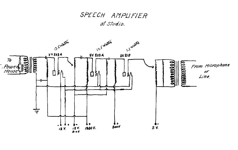
In
the studio control room: The circuit reads from right to left.
Three levels of amplification with volume control were used to
amplify the program audio signal to 17.5 watts, at which point the
program was sent by wire line a short distance to the transmitter.
There is an RF trap at the output transformer to keep the
transmitted signal from interfering with the program.