
A VIRTUAL TOUR OF WEAF
IN 1927
By John Schneider, W9FGH
www.theradiohistorian.org
Copyright 2015 -
John F. Schneider & Associates, LLC
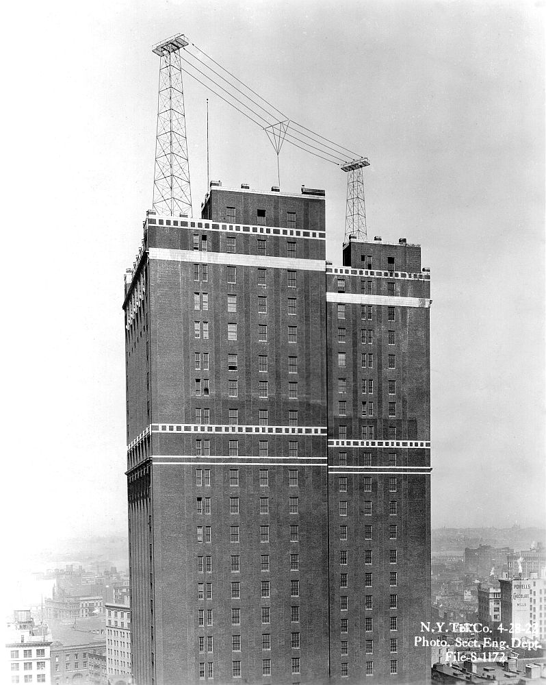
This was the WBAY antenna atop the 24 Walker Street Long Lines building.
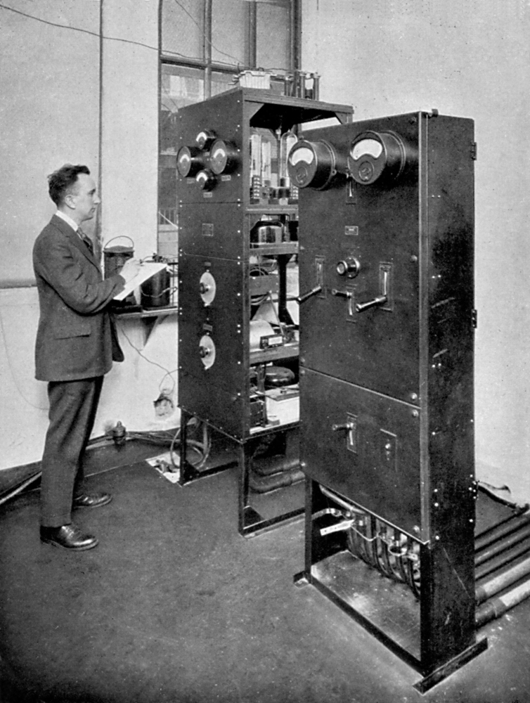
WBAY's 500-watt transmitter at 24 Walker Street.
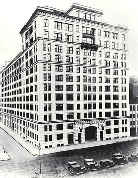
The first home of WEAF was the AT&T building at 463 West Street. This photo was taken in the late teens, before the station’s antenna was built on the roof of the building.
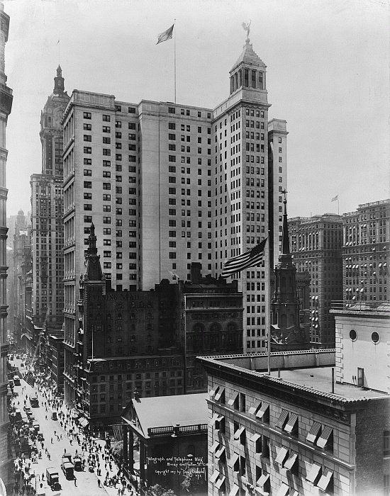
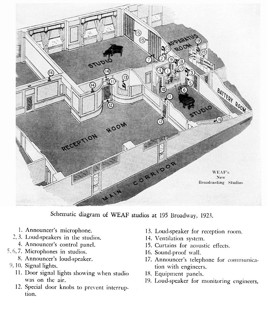
WEAF's studios were located on fourth floor of the AT&T Building at 195 Broadway after 1923 .

The iconic radio
station WEAF in New York City began in 1922 as a grand experiment by the
Western Electric Company, a subsidiary of AT&T. Western Electric was interested in exploiting
its collection of radio patents, which it believed would allow it to corner the
market in the exploding field of radio broadcasting. Specifically, its station was conceived by AT&T as a “toll broadcaster” – it would be a radio-station-for-hire, with
blocks of program time that would be leased to anyone that wanted to
broadcast.
The
original AT&T station was actually licensed as WBAY. The
studio and 500-watt transmitter were located in the company's Long
Lines building at 24 Walker Street, with the antenna on the roof.
The 24-story building rose conspiculously around its surrounding
structures, and engineers believed the building would make an excellent
location for the station. After several months of construction
and testing, broadcasting from WBAY officially began on July 25,
1922. Immediately, it was detected that WBAY's signal coverage
was greatly inferior to that of the Westinghouse station WJZ. The
signal faded especially quickly to the north and south. A
detailed study of the problem revealed that the building's steel girder
infrastructure was resonant at the station's 360 meter frequency, and
was itself absorbing much of the transmitter's power.
Fortunately, AT&T had also installed a transmitter atop its eleven-story 463 West Street building, which had been assigned the call letters WEAF, and that station demonstrated significantly better coverage. The result was that, on August 16, AT&T's toll broadcasting operation was moved to WEAF, and the operations of WBAY were discontinued. Programs continued to originate from the Walker Street building through a telephone line connection. (In 1923, WEAF moved into more elaborate new studios on the fourth floor of the AT&T Building at 195 Broadway.)
On the
technical side, Western Electric was using WEAF as a laboratory for the
development of its commercial broadcasting equipment. WEAF began with 500 watts, but by 1925 it was
using the country’s first 5,000 watt transmitter, a Western Electric prototype.
WEAF was also a pioneer in the early
development of radio networks, as it regularly linked up with its sister
station WCAP in Washington as well as other stations around the Northeast to
create the first “chain broadcasts”. These early WEAF experiments, coordinated with
sister company AT&T, led to the construction of an elaborate national network
of broadcast-quality telephone lines which would become a major source of
revenue for AT&T.
In 1919, AT&T
was one of the original partners in the formation of RCA (the Radio Corporation
of America), along with General Electric, Westinghouse and the United Fruit
Company. However, the marriage of these
companies did not go smoothly, and RCA suffered a great deal of internal
friction between its partner companies. For
one thing, Westinghouse and G.E. had been fierce competitors since the AC-vs-DC
current wars of the 1880s. Additionally, AT&T felt its patent holdings
gave it a monopoly on transmitter technology and radio broadcasting – a point
strongly contested by both GE and Westinghouse, who were also operating their
own pioneering stations. All of this
turmoil finally came to a head in 1926 during a serious of contentious meetings
between the partners that resulted in AT&T exiting the business of radio
broadcasting, and the purchase of WEAF by RCA for $1 million. The partners also agreed that AT&T would
provide broadcast transmission lines to RCA for the creation of a proposed
national radio network.
RCA made
good on that plan in September of 1926, in a powerful move that reinforced its
dominion over radio broadcasting - it formed the National Broadcasting Company
(NBC) as an RCA subsidiary, and created two new national radio networks – the
NBC Red and Blue Networks. WEAF became
the key station for the Red network and WJZ headed the Blue Network. The new networks quickly signed up many of the
most important radio stations in major cities around the country as, and
AT&T settled comfortably into its lucrative new role of supplying NBC with
all of the network lines it needed to feed affiliate stations around the
country. In 1927, all studio operations
of NBC, WEAF, and WJZ were consolidated in beautiful new art deco studios at
711 Fifth Avenue. (They would move again
in 1933 to even more opulent surroundings – Radio City in the new Rockefeller
Center building.)
Within a few
short months, RCA and NBC had become the kings of the radio hill, and they now
turned their attention to improving their two key New York outlets.
SUPER POWER:
RCA now
wanted to lead the nation in the development of “super power” transmitter
facilities for its two stations. The
first high power station in the country was General Electric’s WGY in
Schenectady, New York, which began operating regularly at 50 kW in 1926 and even
experimented with 100 kW in 1927.
However, the Federal Radio Commission would not allow any station having
more than 5 kW to broadcast from inside its city limits for fear of overloading
the public’s still-primitive radio sets.
If RCA was going to increase its stations’ power beyond 5 kW, it would
have to transmit from outside of New York.
The company obtained two rural tracts of land for its stations and contracted
with its partners Westinghouse and General Electric. Westinghouse would build a 50,000 watt
transmitter for WJZ, and GE. would build one for WEAF.
WJZ was the
first station to throw the big switch, which began operating experimentally
with a Westinghouse open-frame transmitter from Bound Brook, NJ, in late 1925. However, the station immediately received 1,500
interference complaints from nearby neighbors, and as a result was not allowed
to operate with more than 30 kW until 1933.
WEAF was the
second station to increase power, broadcasting from a new transmitter site
located in more rural surroundings on Maple Avenue in Bellmore, Long Island, 28
miles East of New York. Construction began
in the summer of 1927, and the new site formally debuted on October 10. Let’s take a virtual tour of that facility.
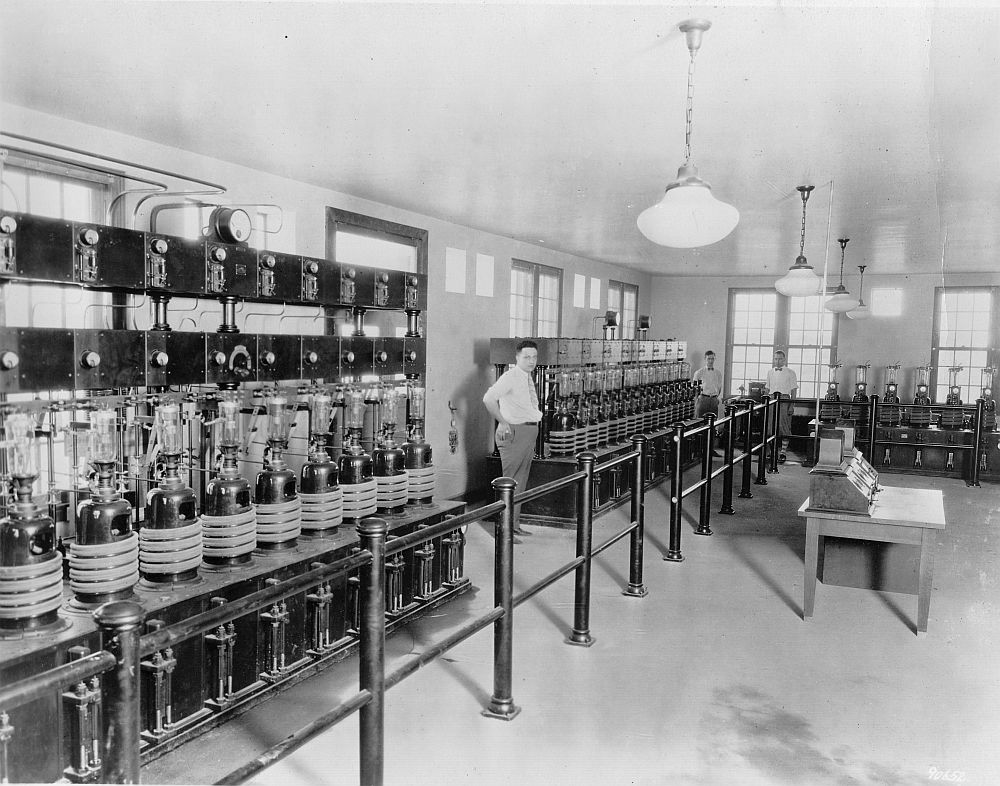
A VIRTUAL TOUR:
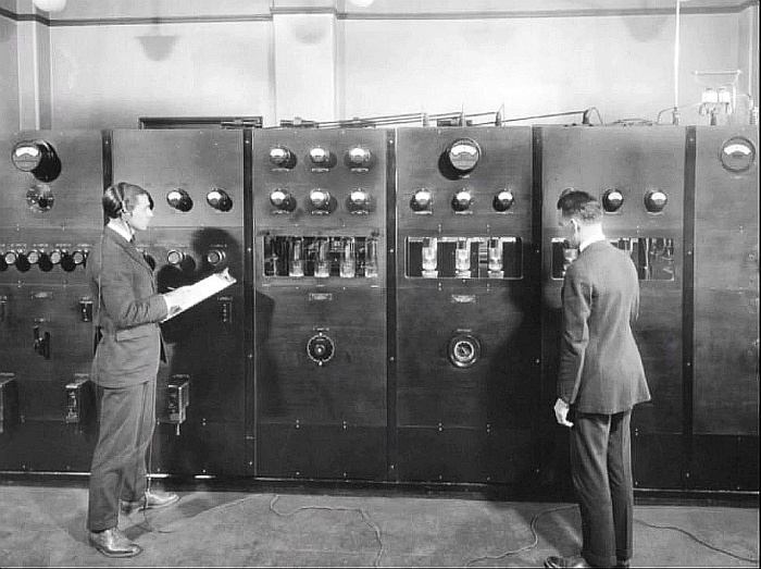
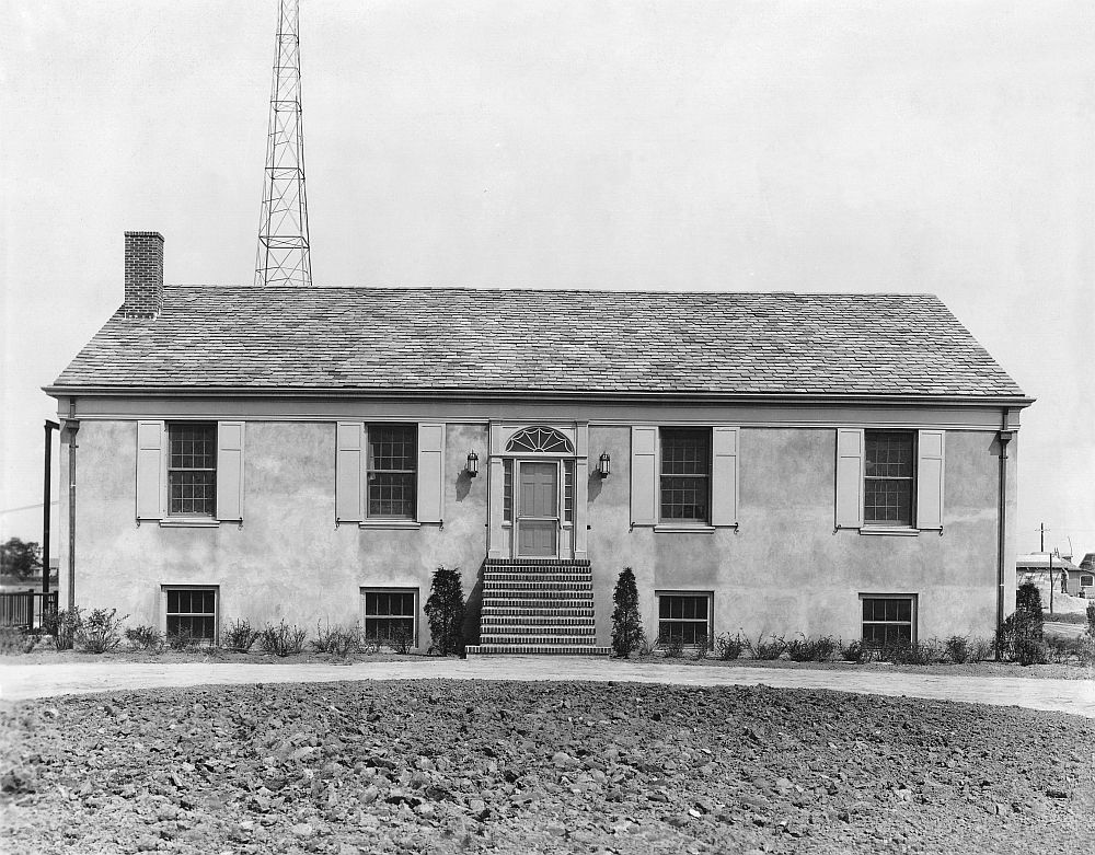
The WEAF transmitter
was housed in a two-story 30x70 ft. stucco building decorated in a colonial
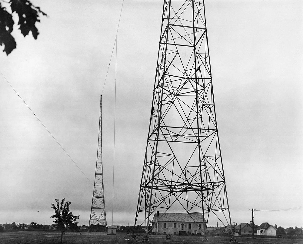
style to blend in with its rural surroundings. Two 300 foot towers supported a single 3/8”
wire antenna, instead of the multi-wire T-type configuration that was typical
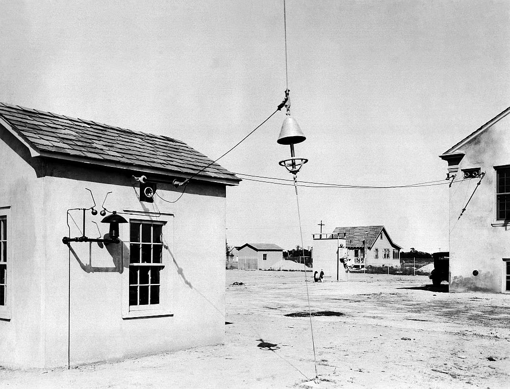
of that era. A center downlead wire
connected the antenna to the tuning house. As an aircraft hazard marking, the towers
were painted in alternating 12 foot bands of black and yellow and illuminated
by floodlights. (This was before orange and white colors we see today were
standardized.)
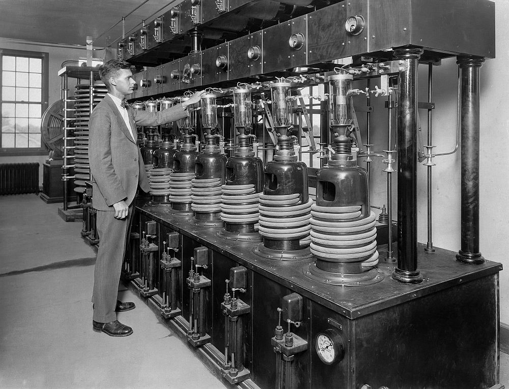
Even though
it was constructed by GE, all the top electronics minds of Westinghouse, GE and
RCA participated in the planning of the new RT-150A transmitter, representing
the apex of radio science in the day. Dr.
Alfred N. Goldsmith of RCA, Dr. E.F.W. Alexanderson of General Electric, and
Frank Conrad of Westinghouse, all participated in its design.
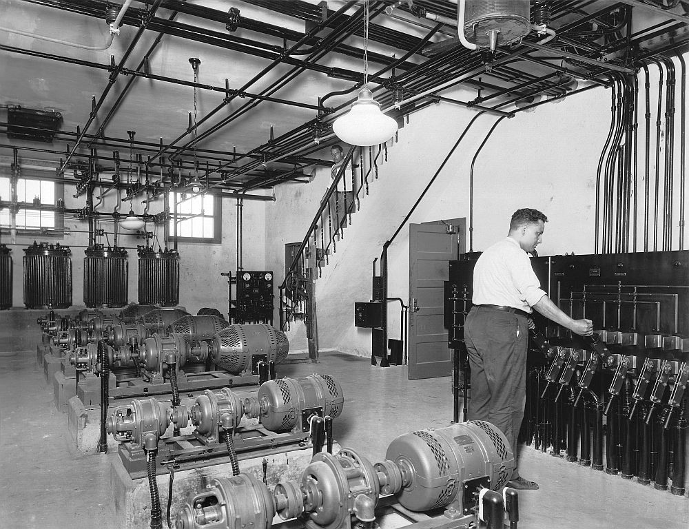
RT-150A TRANSMITTER DESCRIPTION:
- The speech amplifier cabinet (modulator driver)
– with two redundant amplifiers and a transfer switch.
- The crystal controlled oscillator cabinet, whose
three crystals that could be switched to operate either of two oscillators.
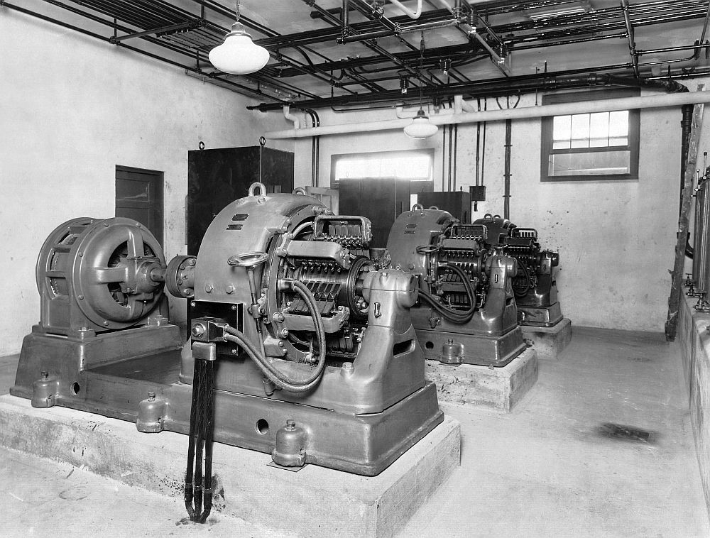
-
An Intermediate RF amplifier, with one 10 kW air-cooled
tube.
-
The RF final power amplifier, in an open frame
assembly
-
The modulator section, in an open frame assembly
-
The high voltage rectifier, in an open frame
assembly
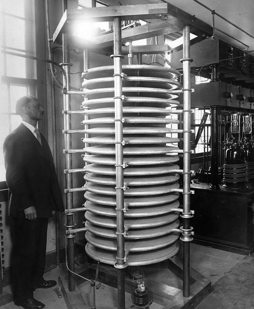
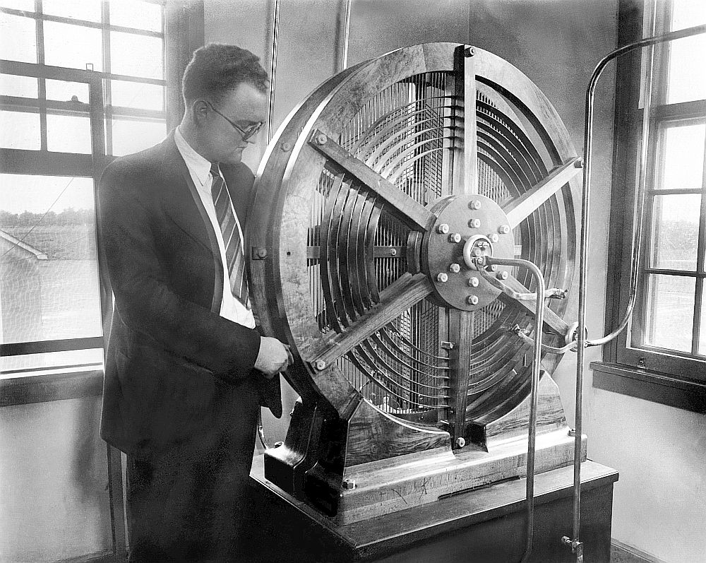
-
The output loading condenser – a large
open-frame multiple-plate air capacitor
-
The output coupling transformer with
electrostatic shield between the windings
-
The antenna tuning unit – located in a small tuning
house under the main antenna downlead
-
A heat exchanger for water cooling system,
located outdoors
-
Redundant pumps and a still for the water
cooling system
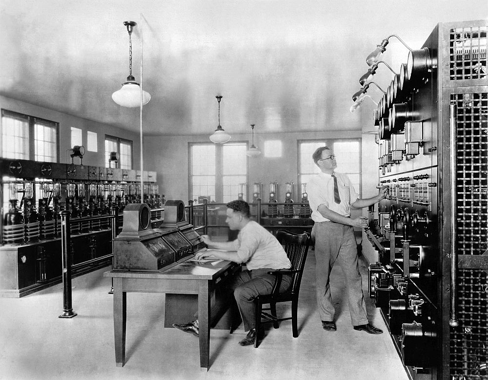
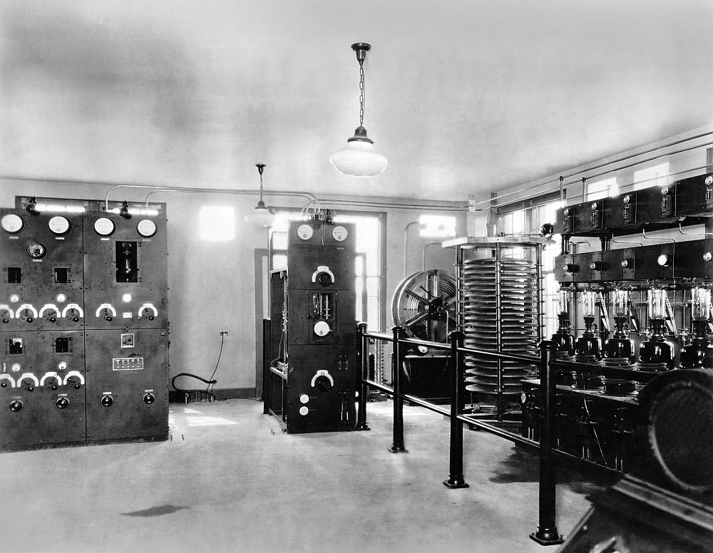
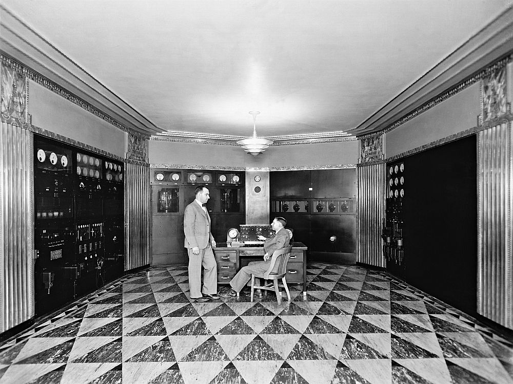
-
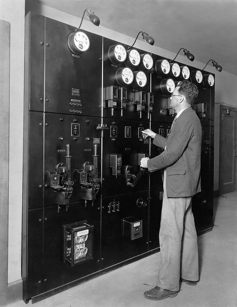
A master power control panel for all transmitter
components
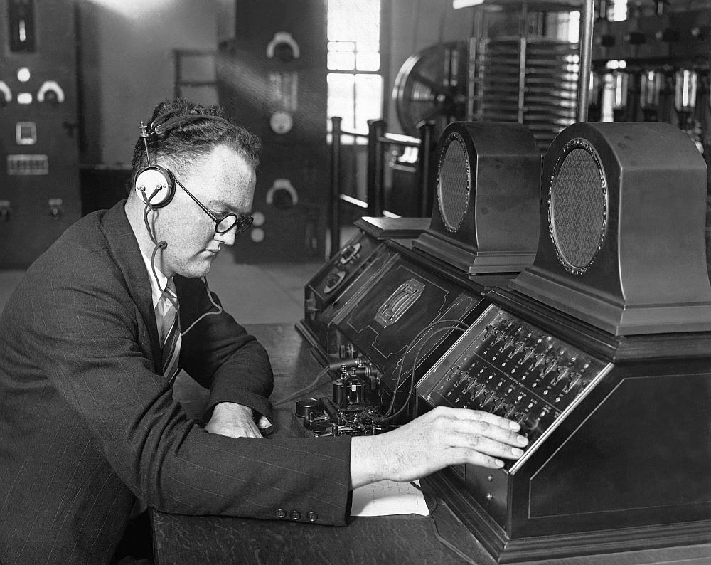
- The operator’s desk
-
Redundant DC motor generators for filaments,
bias, and intermediate voltages
-
A control panel for the motor generators
-
Power supply transformers and reactors
-
Banks of batteries and a battery charger for
low-voltage circuits
-
An oscillograph for monitoring the transmitter’s
modulation (a mechanical predecessor to the oscilloscope).
But there
was another, more fundamental problem with the Bellmore site - its signals were
never very strong in New York City – it was just too far away. Initial reports in 1927 showed that WEAF in
many parts of the city was weaker than from its old 5 kW rig on West Street. Finally, in August 1941, WEAF moved again –
this time to Port Washington, NY – ten miles closer to the city. A new two-tower directional array was put
into operation, and the station’s signal in New York City was finally strong
again. The 50B was moved from Bellmore
to Port Washington, and so the old RT-150A probably sang its swan song by
keeping WEAF on the air during the move.
In November,
1946, NBC changed the station’s call sign from WEAF to WNBC. In 1988, NBC sold the station, and it became
WFAN, which is operated today by CBS Radio.
Since the 1960s, it has broadcast from its present transmitter location
on High Island in the Long Island Sound.
REFERENCES:
- The Airwaves of New York, By Bill Jaker,
Frank Sulek, Peter Kanze
- Commercial Broadcasting Pioneer: the WEAF Experiment, by William Peck Banning, 1946
- "Extracts from the log of station WBAY", by O.B. Hanson and C.H. Clark, 1935.
- America’s New High Power Broadcasting Station”
by A. Dinsdale, “Wireless World”, March 31, 1926.
- “WEAF
superpower plant on L.I. goes on the air”- Brooklyn Daily Eagle, 8/28/1927
- “New 50 kW transmitter of Station WEAF” – Radio
News, November, 1927
- Radio Broadcast Magazine, December, 1927, page
108.
- “WGY: America's New 100kw Transmitter. Satisfactory Results of a Thirty Days'
Special Test” by A. Dinsdale, “Wireless World”, October 5, 1927.
- “’Sparks’
visits WEAF’s new home – Boys Life, December 1927
- “New $300,000 transmitter used by WEAF” – Radio
World – 4/25/31.
- “Pioneer NBC Stations Modernized”- RCA Broadcast
News, April 1932
- Broadcasting Magazine, 3/15/39
- Broadcasting Magazine, 3-15-39
NOTE: This article appeared in the Spectrum Monitor Magazine, December, 2015.