www.theradiohistorian.org
Copyright 2011 - John F. Schneider
& Associates, LLC [Return
to Home Page] (Click on photos to enlarge)
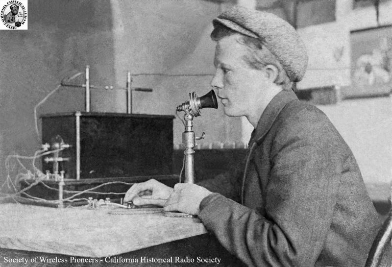
San Francisco, 1902: Thirteen-year-old Francis McCarty is shown
speaking into his invention, the McCarty Wireless Telephone. Although he did successfully transmit the
human voice, the intelligibility was poor because of his reliance on spark
transmitter technology. Successful voice
transmission would have to wait for the development of continuous wave (C.W.)
technology a few years in the future. (California
Historical Radio Society photo)
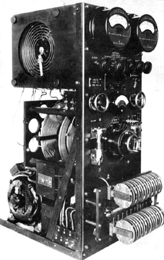
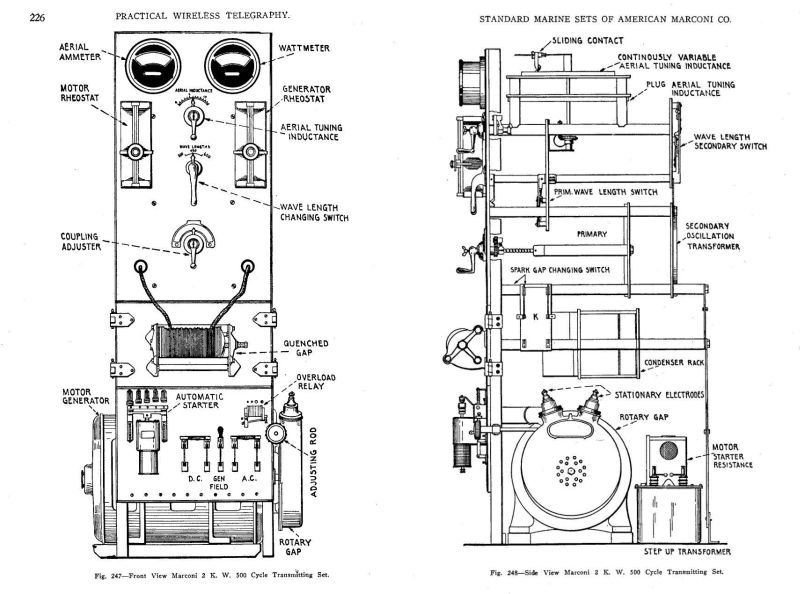
 Front and side views of a typical spark transmitter.

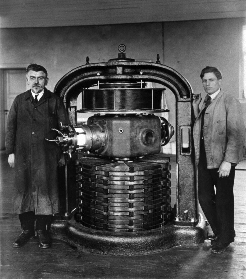
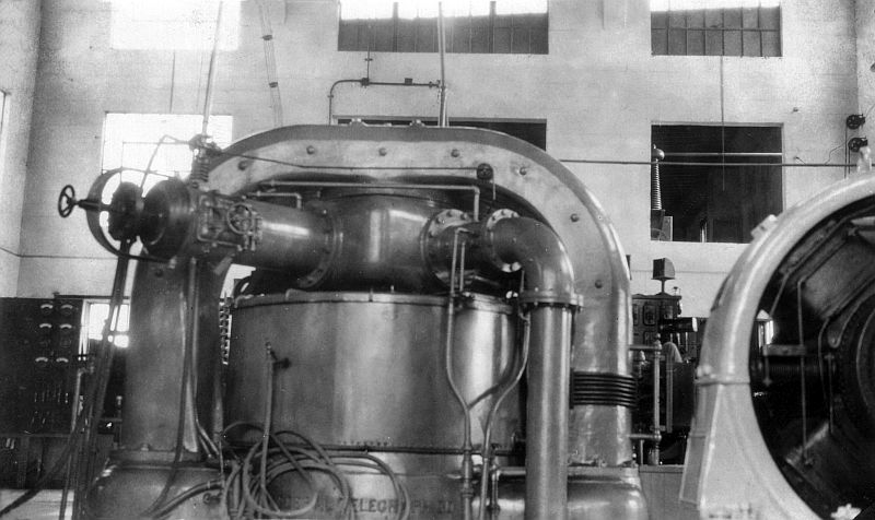
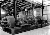 Ernst Alexanderson at General Electric developed
the Alexanderson Alternator, another early transmission system that was capable
of transmitting a continuous wave radio signal before the development of power
vacuum tubes. These monstrous machines were manufactured
between 1910 and the early 1920’s, and several of them remained in operation
through the 1940’s. The last remaining
Alexanderson Alternator, at Grimeton, Sweden, is still operated occasionally
for special events. This photo shows a
pair of 200 kW Alexanderson alternators at RCA Radio Central, Rocky Point, Long
Island.
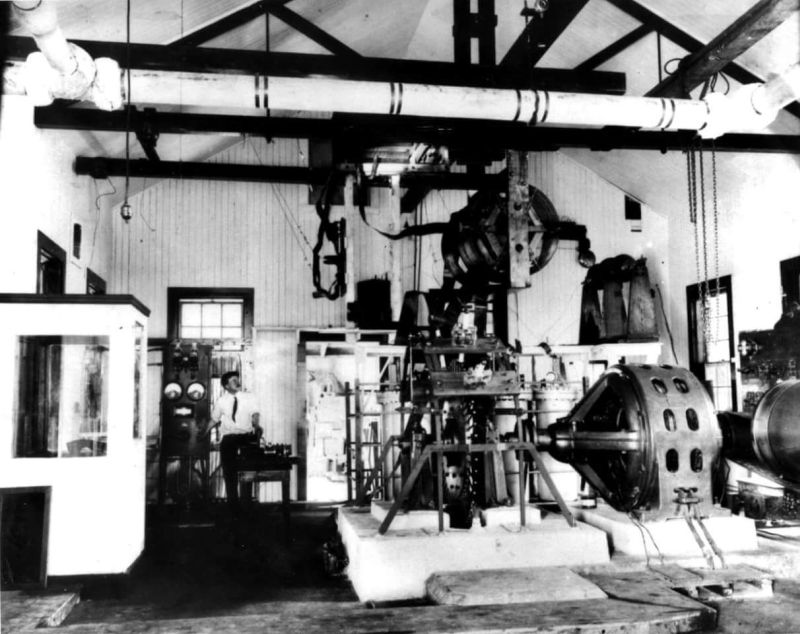
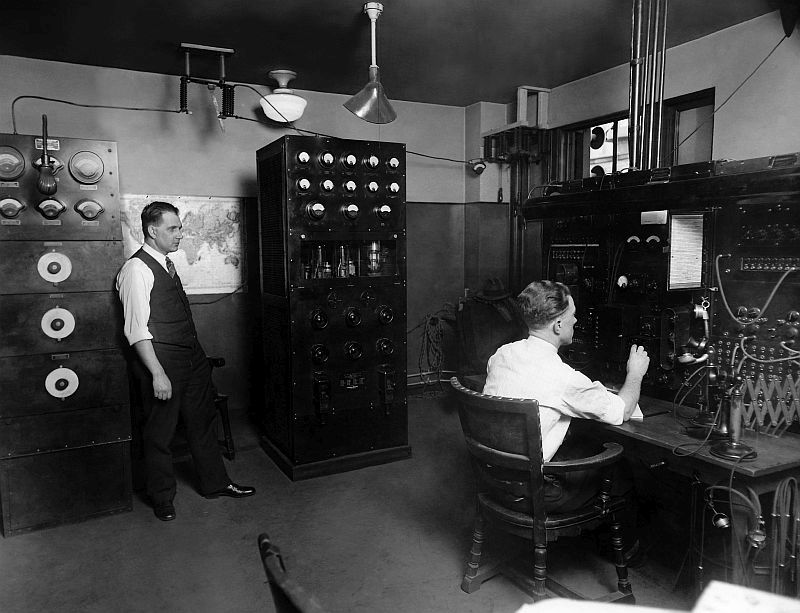
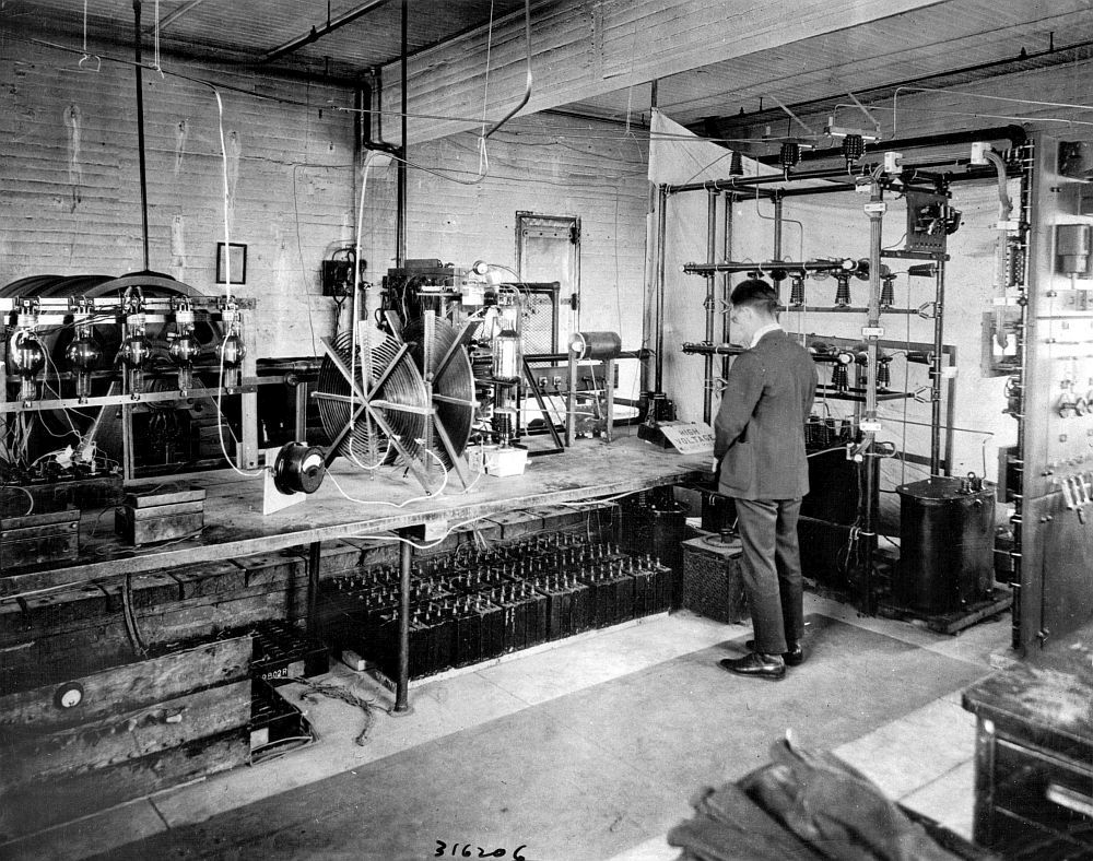
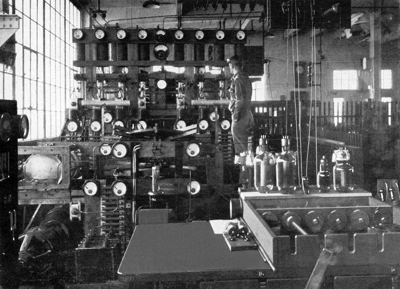
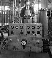
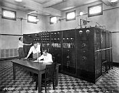
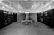
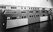
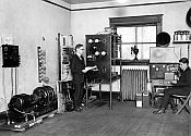 Most broadcast stations in the early 1920’s assembled
their own transmitters. This photo shows
the entire facilities of WRM at the University of Illinois in Champaign. The transmitter (center) received its DC power
from a motor-generator (lower left). The
student announcer (right) is speaking into a converted telephone
microphone. Batteries on the floor
supply the power for the amplifier on the desk.
The two tubes in this transmitter were the only ones owned by the
university, and they were occasionally borrowed during off-air hours by a
professor doing sound-on-film research.
WRM remains in operation today, now using the call sign WILL.
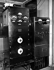
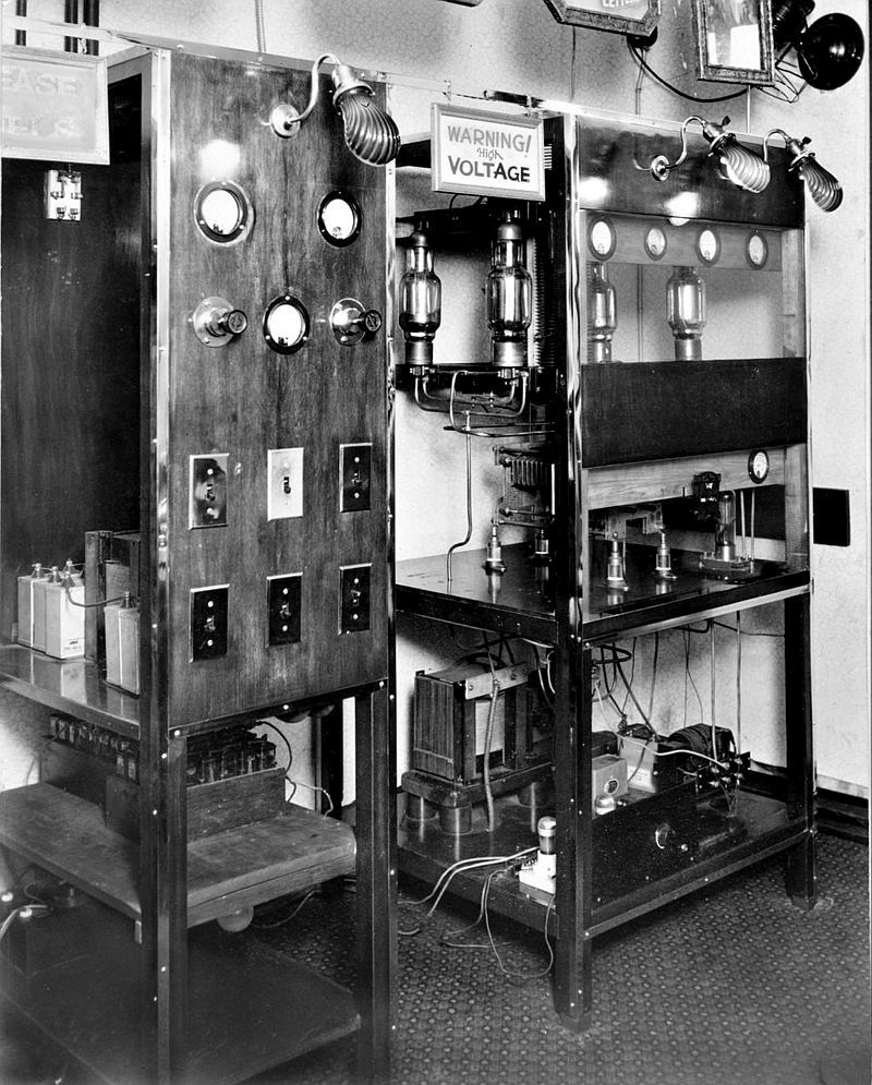
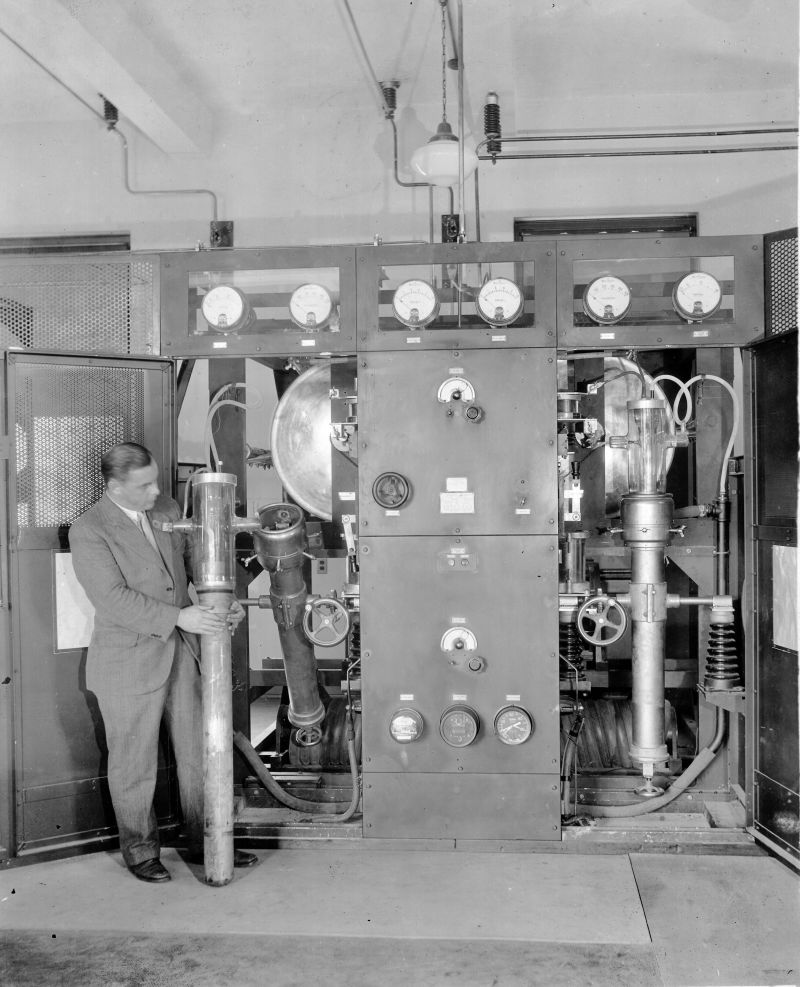
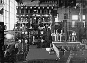
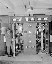
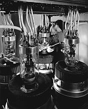
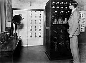 Here is another view of the
Western Electric 6-B transmitter. This
one was installed in 1925 at KPO in San Francisco, located in the Hale Bros.
Department Store on Market Street. One
detail to notice is the marble electrical panel in the background.
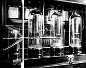
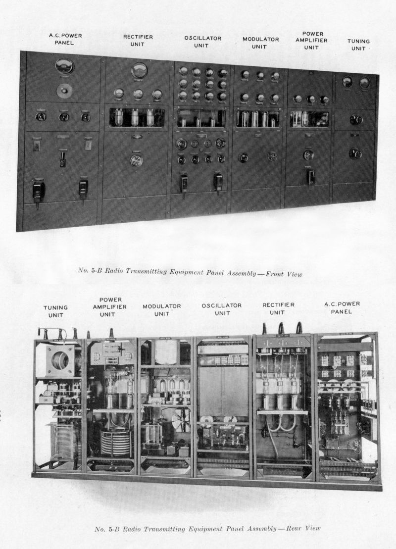
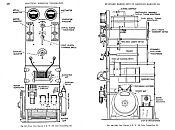
Front and rear views of the Western Electric 5B, the first factory-built 5,000 watt transmitter.
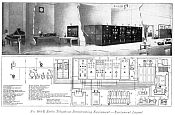
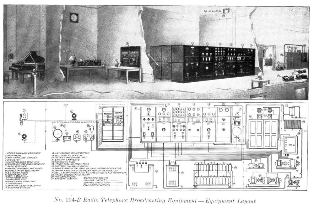
This Western Electric diagram shows the typical installation of a 5B in a radio station..
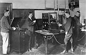
 This image shows a 5B transmitter installation at WMAQ in Chicago.
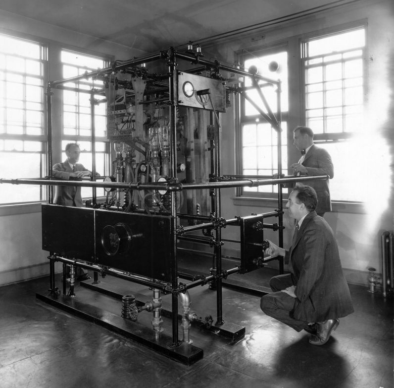
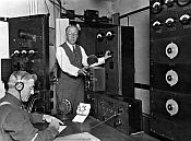
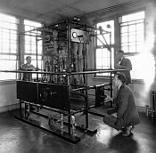
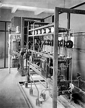
General
Electric put the country's first 50 kW transmitter on the air at WGY in
Schenectady in 1925. Here is a view of that first transmitter at
GE's experimental radio facility in South Schenectady.
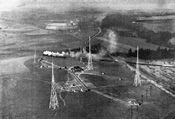
This
is an aerial view of the General Electric experimental radio facility
in South Schenectady, NY, 1926. WGY's first 50 kW experimental
transmitter operated from this location.


|
|
In the beginning,
there was King Spark
The first transmitters grew out of the observation that, if
a continuous chain of sparks was discharged into a tuned antenna circuit, a
signal would be radiated that could be received at a distance and could carry telegraphically-coded
communication. Guglielmo Marconi was the
first to develop a practical communications system using spark transmitters.
There were a few early attempts at using spark equipment to
transmit the human voice. Francis
McCarty in San Francisco developed a crude system between 1902 and 1906, but
the speech quality was poor. This was because
a spark signal consists of a continuous sequence of decaying waves, called
“damped waves”. The signal faded in
intensity as the energy of each spark dissipated, until it was replaced by a new
signal from the next spark. These
“holes” in the signal prevented the transmission of clear intelligent speech. What was needed was a “Continuous Wave”, or
C.W., signal. In the early 1900’s, there
were only two devices that were capable of generating a continuous wave – an
arc transmitter and a high-frequency alternator.
The arc transmitter was conceived by the Danish inventor
Vlademar Poulsen in 1903. It functioned
by generating a continuously-oscillating arc between carbon and copper electrodes
inside a magnetic field, which converted the arc’s high voltage DC to a continuous
wave RF signal in the VLF frequency range.
A number of high power arc transmitters were built by the Federal Telegraph
Company in Palo Alto, California, for the U.S. Navy before and during World War
I.
At about the same time, in nearby San Jose, Charles D.
Herrold was able to broadcast intelligent speech from an arc transmitter by
inserting a microphone between the transmitter and antenna. This crude system of modulation operated on
the principal that sound waves caused the resistance of a carbon microphone
element to vary, producing a corresponding change in antenna current. The complication was the great amount of heat
dissipated in the microphone; Herrold solved this by using an array of six
water-cooled mics in parallel. This
method only created a modulation level on the order of ten percent. Even so, using this crude system Herrold was
able to maintain a schedule of weekly music broadcasts to local ham radio operators
between 1912 and 17.
The second device able to generate a continuous wave signal was
the high frequency alternator, first developed by Ernst Alexanderson of General
Electric for Dr. Reginald Fessenden. This
was a completely mechanical system –a high speed motor was used to drive a
specially-constructed alternator, producing an A.C. current that oscillated at very
low radio frequencies (20 to 100 kHz). Fessenden
is famously said to have used an early version of his alternator to broadcast
speech and music to vessels in the Atlantic on Christmas Eve, 1906, utilizing
the same microphone absorption method as Herrold. Over the next several years, G.E. developed
alternators up to 200 kW that were used by the Navy, RCA, and other major
communications actors for high speed CW communication well into the 1940’s.
The Vacuum Tube Changes
Everything!
The invention of the “Audion” triode vacuum tube by Lee de
Forest in 1906 created a revolution in radio communications. Its ability to function as both an oscillator
and amplifier opened doors to the creation of a practical all-electronic speech
transmitter. In 1913, de Forest sold the
commercial rights to his tube to AT&T, where the erratic device was further
developed into a practical and stable product.
World War I saw additional development, and the vacuum tube was quickly
adapted for use in both transmitters and receivers.
Lee de Forest was also one of several pioneers in early
experimental broadcasting, using his vacuum tube transmitter to broadcast recorded
music from his station 2XG in the Bronx starting in 1916, and later
transmitting live opera music from 6XC in San Francisco in 1920.
Many amateur radio operators, prohibited from transmitting
from 1917 to 1919 due to wartime security measures, entered the armed forces as
radio operators, and they considerably enhanced their knowledge of tube
electronics in those years. When the wartime moratorium was lifted, dozens of these
hams experimented with audio transmission utilizing war surplus tubes. A number of these hams joined the ranks of
the first commercial broadcasters as the radio boom swept the country in
1920-22. Several of the country’s first
broadcasting stations - including WWJ, WHA, KDKA and KJR - grew out of amateur
stations.
In 1922, radio broadcasting became an overnight sensation,
as millions of average Americans were bit by the radio “bug”. Between March and June, the number of radio
stations swelled from 67 to nearly 400. Most
of these stations operated with home-brewed transmitters of varying power and quality,
utilizing a variety of circuit designs. Available transmitting tubes ranged in power from
ten to 250 watts input, and so it was common practice to operate several tubes
in parallel to achieve higher powers.
The results were often unstable and unreliable, as most of these early
rigs were nothing more than high-power free-running oscillators. Modulation was accomplished with a high power
Class A modulator stage using the Heising “Constant Current” method: the plate current for both the RF and modulator
stages was delivered through an inductor that resisted changes of current with
varying modulation, so that modulation peaks would cause a corresponding drop
in the PA voltage. These transmitters
were typically capable of modulation peaks of only about 50%.
The first factory-built broadcast transmitter was the Model
1-A, released by the AT&T subsidiary Western Electric in 1921. Like many of those rudimentary home brew
rigs, it was a 500 watt free-running oscillator with Heising modulation. (500 watts was considered “high power” in
1921.) Four 250-watt 212-A vacuum tubes
provided the carrier power and modulation. High power rectifier tubes did not yet exist,
and so the filament and plate voltages were supplied from DC motor-generators. The 1-A’s first users were AT&T’s WEAF in
New York and WWJ in Detroit. These
stations -- like most early broadcasters – transmitted from “flat top”
horizontal wire antennas, which were an outgrowth of the old maritime spark
antennas. Because the antenna
capacitance was part of transmitter’s tuned circuit, they would drift off frequency
whenever the antennas blew in the wind.
Western Electric resolved this problem by adding an output tuning
network, and the resulting transmitter, now called the model 1-B, was soon
installed at more than thirty of the country’s most important radio stations.
Nonetheless, the majority of the country’s broadcasters were
still using homemade transmitters, and they were legally in violation of
patents that AT&T controlled on a number of critical transmitter
circuits. AT&T attempted to enforce
its patent rights by demanding these stations pay royalties. It also alleged that it had the exclusive right
to broadcast on-air advertising, and demanded that all other stations cease the
broadcasting of advertising messages.
The proposed license agreement was so onerous that most broadcasters
refused to sign it. As a test case, AT&T
sued the New York broadcaster WHN, and although it ultimately won its lawsuit,
the negative publicity created by these heavy-handed methods finally caused
AT&T to drop its patent enforcement efforts. Nonetheless, its hold on a number of key patents
kept other companies out of the transmitter business. (An exception was made for its RCA patent
pool partners Westinghouse and General Electric, but they could only make
transmitters for their own stations.) It
wasn’t until the patents expired at the end of the 1920’s that RCA, de Forest
and a few other smaller manufacturers could enter the field and supply
factory-built transmitters.
When first organized in 1919, RCA was simply a pool of the
radio patents controlled by General Electric, Westinghouse, AT&T, and a few
smaller players. Subsequently, most all the
development of the more modern commercial transmitter technologies grew out of
laboratory research conducted at Western Electric, G.E. and Westinghouse in the
1920’s and early 1930’s. Each of these
companies operated their own broadcasting stations and they used them as
research test beds, exchanging innovations among themselves. Particularly, G.E.’s broadcast station WGY
in Schenectady was a key test bed for the development of high-power transmitter
tubes and more stable circuits. Thanks
to that company’s work, a second generation of transmitters emerged in the late
1920’s.
The Transmitter
Come of Age
In 1931 the Federal Radio Commission issued two new
regulations governing broadcast transmitters.
General Order 111 required stations to modulate a minimum of 75%, and
General Order 116 required stations to maintain their carrier frequencies
within +50 Hz to eliminate heterodyne whistles on the broadcast
band. The old free-running oscillator rigs
became obsolete overnight, particularly due to the frequency stability
requirement. Their usual method of
frequency control was for the operator to adjust the transmitter’s frequency from
a front-panel knob while zero-beating the transmitter’s signal against a reference
crystal oscillator, but they would usually quickly drift off frequency
again. The stations that were measured
off-frequency were fined, and several station licenses were even revoked. Almost overnight, the nation’s installed base
of broadcast transmitters was replaced with new transmitter designs using
crystal-controlled RF oscillators, a technology recently developed by the G.E.
labs in Schenectady. Many small stations
couldn’t afford the investment, and they either disappeared or were merged into
larger operations.
About 1928, Western Electric introduced its revolutionary model
6-B one kilowatt transmitter. It
utilized a Master Oscillator-Power Amplifier (MOPA) design, driven by an
oven-controlled low power crystal oscillator stage. Heising modulation was applied at a mid-level
stage, followed by a Class “A” final amplifier using a single 228-A
water-cooled tube. It was capable of
modulation peaks approaching 100%. Hundreds of these transmitters were
installed at broadcast stations around the country, and many of them continued
in operation through World War II. That
same year, Western Electric introduced its model 5-C, a 5,000 watt transmitter
housed in an imposing row of six cabinets.
This was the first mass-produced factory-made transmitter to produce its
PA voltage with rectifier tubes instead of motor-generators.
By the mid 1920’s, several clear-channel stations were
experimenting with the 50 kW power level, enjoying nearly-nationwide coverage
on their privileged frequencies. WGY was
the first station to achieve this power level experimentally in July, 1925, using the call sign 2XAG.
The transmitter was built by GE's Radio Engineering Department at its
experimental facility at South Schenectady. Three shortwave
stations also operated from this location. In subsequent years,
GE conducted further tests from this site at 100 kW (1927), 150 kW and
200 kW (1930). For its part, RCA contracted with both Westinghouse
and G.E., with each designing and building one high-power transmitter for its
flagship New York stations, WJZ and WEAF.
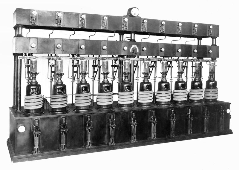
The Westinghouse unit went on the air at WJZ in Bound Brook, NJ, in
November, 1925. It was a conventional 50
kW self-power oscillator in an open-frame design utilizing twenty water-cooled
tubes. (See the Spectrum Monitor article, July 2016) For its part, G.E. delivered its more innovative
RT-150A to WEAF at Bellmore, Long Island.
It also combined 20 water cooled tubes in an open frame construction,
but the resemblance ended there. A dedicated
high-power crystal-controlled transmitter excited the final amplifier, and the
modulation was accomplished at the final RF stage using a high-powered
modulator and Heising modulation. It
also used mercury-vapor rectifier tubes instead of motor-generators for its PA
power supply. It was clearly superior to
the Westinghouse design, and RCA soon ordered a second RT-150 for WENR in
Chicago. (Spectrum Monitor article, December 2015)
In 1928, Western Electric joined the high power club with its model 7-A 50
kW AM broadcast transmitter. It consisted of a 5 kW modulated
driver followed by a final amplifier. Its ten cabinets held 25
tubes, including fourteen that were water-cooled. Its frequency
was crystal-controlled, and it was said to be the first transmitter
capable of 100% modulation. The transmitter was developed at
Western Electric's radio test facility in Whippany, NJ, and operated
sporadically during its development under the call sign 3XN in late
1927. On January 9, 1928, an open house tour of facility was
held for the members of the Institute of Radio Engineers. The
first commercial installation of the 7-A transmitter was made at WLW in
Cincinnati in August of 1928.
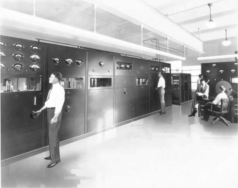
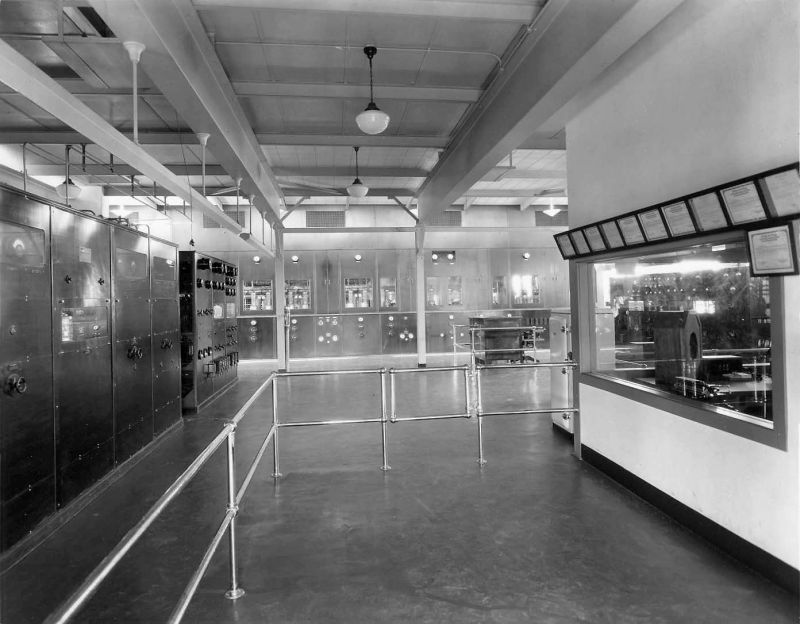
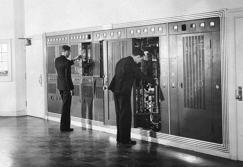
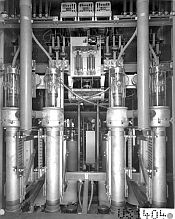
All the design innovations created for these early custom
transmitters were quickly rolled into the first 50 kW factory-built design - a
joint effort of General Electric, Westinghouse and RCA. The 50-B – first branded as a General
Electric product, but later marketed under the RCA label, was fabricated at both
the G.E. and Westinghouse factories. This
massive rig required an RCA-designed two story building to house it. The main unit, on the upper floor, consisted
of four groups of operating panels: the
first was a complete RCA 5-B five kilowatt transmitter, which featured dual
crystal oscillators and mid-level Heising modulation. It was followed by a 50 kW Class A linear
amplifier with two water-cooled UV-862 tubes, each rated at 50 kW. The third set of panels contained a row of six
mercury vapor rectifier tubes for the plate voltage, and the fourth panel was
for overall power control. On the lower
floor, motor-generators provided DC power for the tube filaments. Distilled water cooled the tubes, with water
pumps and a heat exchanger feeding an outdoor spray pond. The first 50B went to WTIC in Hartford in
1929 - it thereafter became an industry standard product, installed at most of
the major clear channel stations in the country, including all of the NBC-owned
50 kW stations. A number of these systems
remained in use until 1960s.
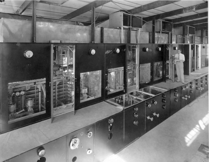
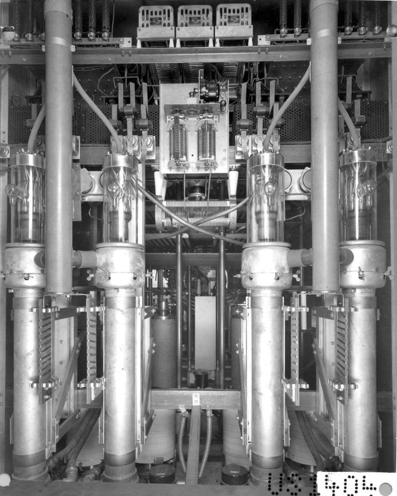
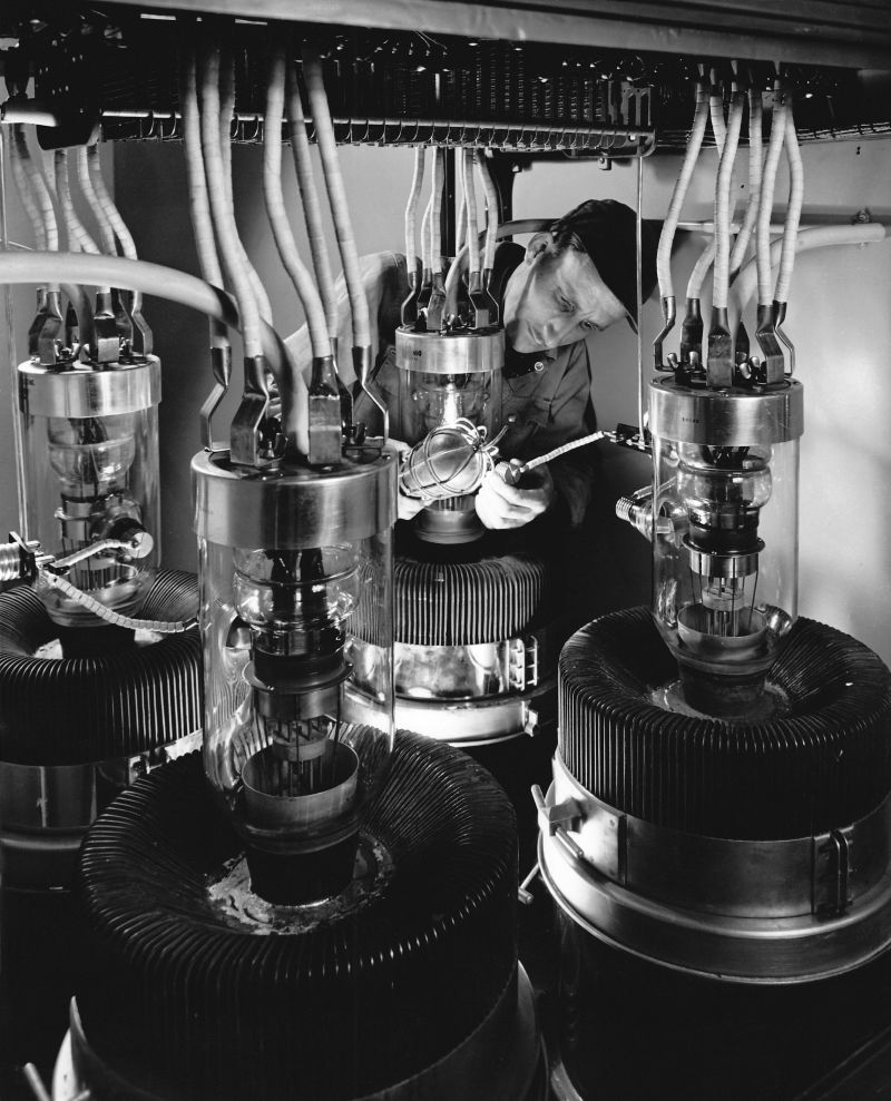
WLW’s Monster
Transmitter
In 1932, this trio of American electronics manufacturers
took on their biggest broadcast assignment yet –a massive 500 kW transmitter
custom-built for Powel Crosley’s WLW in Cincinnati. That June, the Federal Radio Commission
granted WLW’s request for experimental “super power” operation, and Crosley tendered
his order for the country’s largest AM broadcast transmitter. RCA, Westinghouse and G.E. collaborated on
the design, each building sections of the system. WLW’s existing Western Electric 7-A 50 kW unit
became the driver for a huge modulated final amplifier containing twelve
water-cooled 100 kW PA tubes, and with another eight serving as modulator
tubes. To reduce the massive power consumption of such a huge system, high-level
Class “B” modulation was employed. This technique,
invented by Loy Barton with his patent assigned to RCA in 1932, substituted a
modulation transformer in place of the customary Heising reactor at the final
amplifier stage. This allowed the use of
a Class “B” modulator and Class “C” power amplifier, resulting in considerable
power savings.
WLW operated at 500 kW from 1934 to 1939 under an
experimental license that was terminated when the FCC decided to establish 50
kW as the ceiling for all United States AM radio stations. No other AM broadcast band station in the
United States has operated with as much power, either before or since. Although it has been unused since 1939, this
transmitter still sits in the WLW transmitter building in Cincinnati.
The Search for
Power Efficiency
We can consider the WLW transmitter to be a third-generation
design due to its use of High-level Class “B” modulation. The previous generation of transmitters generally
delivered good quality, stable signals with reliable operation and clean audio
quality. The implementation of Class “B”
modulation represented the first step towards improved efficiency and reduced
power consumption. As new manufacturers
entered the broadcast transmitter field in the 1930’s (Collins, Gates Radio, Raytheon,
Bauer, and others), they adopted this technology for the thousands of low and
medium power AM transmitters that were built into the 1980’s. But at 50 kW, the physical size and cost of
the huge modulation transformers was a disadvantage, and their high electric
power cost was still an issue for the country’s hundred-plus 50 kW AM stations. The search continued for even more efficient
and cost-effective transmission systems.
RCA took a step forward with the introduction of its
high-efficiency air-cooled tubes, which eliminated the elaborate and
troublesome water cooling systems of earlier designs. In 1947, RCA introduced its model BTA-50F,
which utilized its 5671 thoriated tungsten filament tube. The transmitter was quickly adopted by a
number of important stations in the U.S. and around the world. Westinghouse and G.E. also introduced similar
designs.
In an effort to eliminate the modulation transformer and further
reduce power consumption, Western Electric introduced its Doherty power
amplifier in 1938. Invented by William
H. Doherty of Bell Telephone Labs, it utilized two Class “B” final amplifier tubes
– one generated the signal up to the carrier level, and the other added the
extra power needed for modulation peaks.
The first Doherty transmitter was installed at WHAS in Louisville, and
it was exclusively utilized by Western Electric until 1953, continued
afterwards at Continental Electronics when that company purchased Western’s
transmitter division. Continental built
its updated versions of the Doherty amplifier through the 1990’s.
Another efficiency improvement was outphasing modulation, based
on the 1935 design of Frenchman H. Chireix, and first developed by McClatchy
engineers in 1948 at the company’s station KFBK in Sacramento. This method completely eliminated the high
level modulation section. Instead, the
outputs of two Class “C” tube amplifiers were combined 135 degrees out of
phase. Phase modulation was applied to
each amplifier at a lower power stage, so that the amplifiers were in phase on
positive peaks (adding), and 180° out of phase on negative peaks (canceling).
Adopted by RCA, the technology was marketed under the Ampliphase brand name and
sold in various models between 1956 and 1978.
Today, the most commonly used AM technology is Pulse Width
Modulation (PWM), first introduced in 1978 by the Broadcast Division of Harris
Corporation (formerly Gates Radio Co., now known as GatesAir). This design utilizes high frequency pulse
switching of tube’s plate voltage, with the duty cycle (width) of each pulse
corresponding to the modulation percentage.
This pulse train then passes through a low pass filter that removes the
pulses and delivers smooth modulated DC to the final amplifier. First implemented in the Harris MW-50 tube transmitter,
it has since been adapted by most manufacturers to today’s solid state MOSFET
power amplifiers. (GatesAir, Nautel,
Broadcast Electronics, several others).
In 1991, Harris also developed an innovative digital modulation method which
it applied to its solid state DX-10 and DX-50 transmitters. In this technology, analog audio is converted
to digitized data which turns on and off a series of low power solid state
amplifier modules that are added to create the modulated waveform.
These evolutionary developments in transmitter design – new
modulation methods, better cooling systems, and solid state power amplifiers –
have seen the overall transmitter efficiency (AC in to RF out) increase from
under 25% in the early 1930’s to nearly 90% today. Along the way, many of the technologies
developed for AM broadcasting also found their way into products designed for
the communications, aircraft, and amateur markets. A few technologies became obsolete and
disappeared, only to reappear later in a new form – as witness the modern liquid-cooled
FM and TV transmitters. While the future
of the legacy AM band is uncertain as it approaches its 100th
birthday, it’s certain that many of the technologies developed for that
industry will continue to live on in other applications.
RESOURCES:
- Big Business and Radio by Gleason L. Archer, 1939
- Commercial Broadcasting Pioneer: The WEAF Experiment, 1922-26 by William Peck Banning, 1946
- “United States Early Radio
History”, by Thomas H. White:
- Wikipedia:
- “Federal Radio Commission,
Fifth Annual Report to Congress”, 1931
- “Radio Telephone Broadcast
Equipments (1-A and 2-A)”, a brochure published by Western Electric Company,
May, 1922.
- “Radio Telephone Broadcast
Equipments (106-B)”, and “Radio Telephone Broadcast Equipments (105-C)”,
brochures published by Western Electric Company, 1928.
- "3XN",
booklet prepared for the Institute of Radio Engineers for their tour of
the Western Electric facility at Whippany, NJ, January 9, 1928.
- "Spanning a Continent" booklet, General Electric, July, 1926.
- “Radio News” Magazine,
October, 1927 - “New Experimental 100 kW Transmitter at Schenectady”
- “Radio Digest” Magazine,
8-29-1925 – “General Electric Company Builds Big Laboratory for Transmission
Study”
- “Radio Digest” Magazine, 9-12-1925. - “High Power
Downs Static, Tests Show”
- “Powerful Station Reaches Far
in Day – WJZ Uses 50,000 Watts, Hits Texas at Noon” – “Radio Digest” Magazine,
12-5-1925.
- “QST” Magazine, October, 1929
– “WTIC, America’s Most Modern Broadcasting Station”.
- "Radio World"
Magazine, July 17, 2007 - "Loy Barton, a Forgotten Radio Pioneer", by
James E. O'Neal
- “Proceedings of the Institute
of Radio Engineers”, Vol. 22, No. 10, October 1934, pg. 1151 – “The WLW 500
Kilowatt Broadcast Transmitter”.
- RCA Broadcast News No. 119,
Feb. 1964, “Ampliphase … For Economical
Super-Power AM Transmitters” by D.R. Musson.
NOTE: This article originally appeared in the October, 2018 issue of "The Spectrum Monitor" magazine (Vol. 5, No. 10)
|